Kia Sportage: SRSCM / SRS Control Module (SRSCM) Repair procedures
Kia Sportage QL (2015-2026) Service Manual / Restraint / SRSCM / SRS Control Module (SRSCM) Repair procedures
| Removal |
| 1. |
Remove the Ignition from the vehicle.
|
| 2. |
Disconnect the battery negative terminal and wait for at least thirty
seconds before beginning work.
|
| 3. |
Remove the floor console.
(Refer to Body (Interior and Exterior) - "Floor console")
|
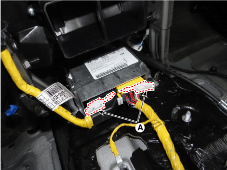
| 4. |
Disconnect the Supplemental Restraint System Control Module (SRSCM)
connector (A).
|
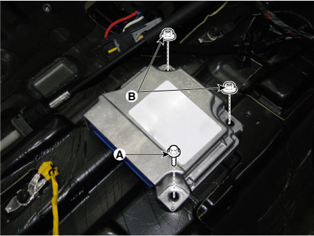
| 5. |
Loosen the bolt (A) and nuts (B) and then remove the Supplemental Restraint
System Control Module (SRSCM).
|

| Installation |
| 1. |
Remove the Ignition from the vehicle.
|
| 2. |
Disconnect the battery negative terminal and wait for at least thirty
seconds before beginning work.
|
| 3. |
Install the SRSCM with the SRSCM mounting bolt (A) and nuts (B).
|
| 4. |
Connect the SRSCM harness connector.
|
| 5. |
Install the floor console.
(Refer to Body - "Floor console")
|
| 6. |
Reconnect the battery negative terminal.
|
| 7. |
After installing the SRSCM, confirm proper system operation:
Turn the ignition switch ON; the SRS indicator light should be turned
on for about six seconds and then go off.
|
| Variant coding |
After replacing the SRSCM, the “Variant Coding” must be performed.
|

Variant coding Procedure
| ■ On-Line type on KDS/GDS |
| 1. |
Ignition "OFF", connect KDS/GDS.
|
| 2. |
Ignition "ON" & Engine "OFF" select vehicle name and airbag system.
|
| 3. |
Select Variant coding mode.
|
| 4. |
Follow steps on the screen as below.
|
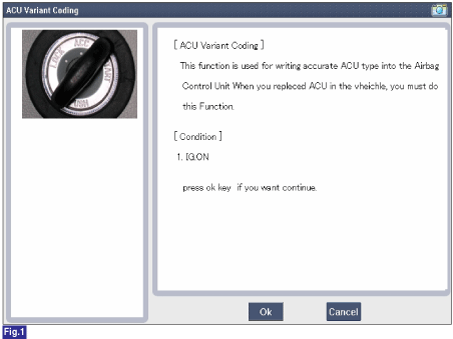
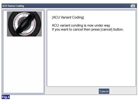
1) Initial ACU Variant Coding screen
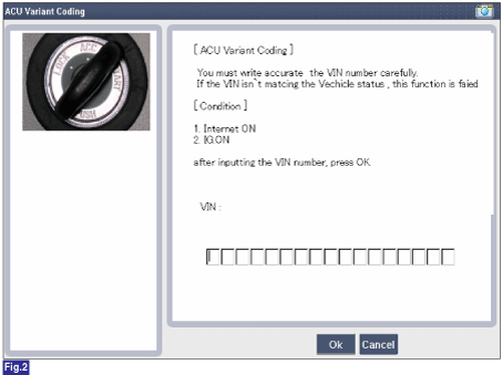
2) VIN Code entering screen
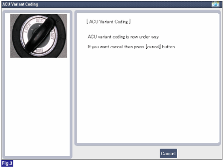
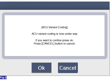
3) Variant coding's proceeding screen-1
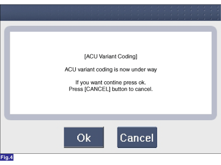
4) Variant coding's proceeding screen-2
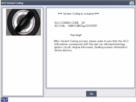
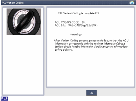
5) Variant coding is completed
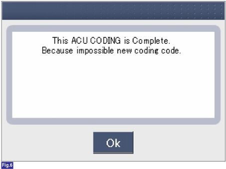
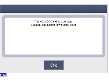
1) This screen is opened when you try the variant coding again on the
SRSCM which has bee performed variant coding.
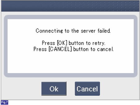
2) Screen of communication failure
|
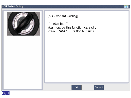
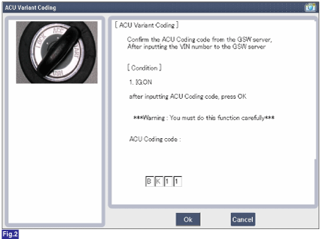
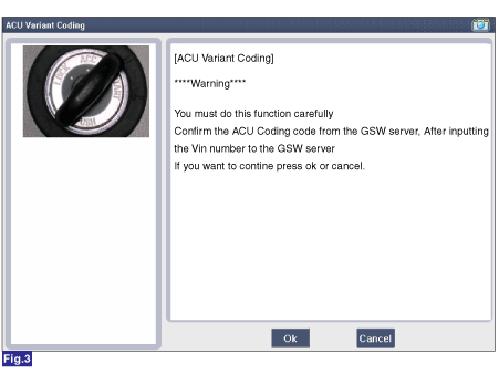
■ Off-line type on KDS/GDS (This can be used when not connecting to internet)
1) Initial ACU Variant Coding screen
2) ACU Coding Code entering screen
3) Screen of rechecking ACU Coding code's entering
4) Variant coding's proceeding screen-1
5) Variant coding's proceeding screen-2
6) Variant coding is completed
1) This screen is opened when you try the variant coding again on the
SRSCM which has been performed variant coding.
|
 SRS Control Module (SRSCM) Components and components location
Components
1. Supplemental Restraint
System Control Module (SRSCM)
...
 Front Impact Sensor (FIS) Description and operation
Description
•
The front impact sensor (FIS) is installed in the Front End Module (FEM).
They are remote sensors that detect acceleration due to a collision
...
Other information:
Kia Sportage QL (2015-2026) Service Manual: Coil Spring Repair procedures
Removal 1. Remove wheel nuts, wheel and tire (A) from hub. Tightening torque: 107.9 - 127.5 N·m (11.0 - 13.0 kgf·m, 79.6 - 94.0 lb·ft) ...
Kia Sportage QL (2015-2026) Service Manual: Line Pressure Control Solenoid Valve Components and components location
Component Location 1. 26 Brake Control Solenoid Valve (26/B) 2. 35R Clutch Control Solenoid Valve (35R/C) 3. Underdrive Brake Control Solenoid Valve (UD/B) 4. Overdrive Clutch Control Solenoid Valve (OD/C) 5. SS-A Solenoid Valve (ON/OFF) 6. ...
Copyright © www.ksportagegl.com 2015-2026
