Kia Sportage: Automatic Transaxle Control System / Inhibitor Switch Repair procedures
Kia Sportage QL (2015-2026) Service Manual / Automatic Transaxle System / Automatic Transaxle Control System / Inhibitor Switch Repair procedures
| Inspection |
Inspect the following items by referring to inspection flow chart.
(Refer to Inhibitor Switch - "Troubleshooting")
|

| 1. |
Check the diagnostic trouble codes (DTC) using KDS/GDS.
|
| 2. |
Check that "N" range setting matches.
(Refer to Inhibitor Switch - "Installation")
|
| 3. |
Check the free play for shift cable.
(Refer to Shift Cable - "Installation")
|
| 4. |
Check the condition of connector.
|
| 5. |
Inspect the ground of rear combination lamp circuit.
|
| 6. |
Inspect the wiring connection of junction box power terminal and fuse
lamp.
|
| 7. |
Check the inhibitor switch circuit signal.
Signal Code Table
|
| Removal |
| 1. |
Shift the gear to "N".
|
| 2. |
Remove the battery and battery tray.
(Refer to Engine Electrical System - "Battery")
|
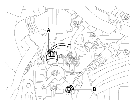
| 3. |
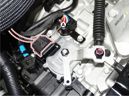
Disconnect the inhibitor switch connector (A) and loosen the shift cable
mounting nut (B).
|
| 4. |
Remove the manual control lever (B) and the washer after removing a
nut (A).
|
| 5. |
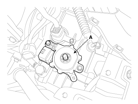
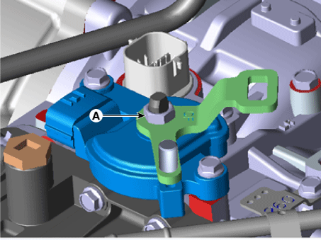
Remove the inhibitor switch (A) after loosening the bolts.
|
| Installation |
| 1. |
Check that the gear is shifted to "N".
|
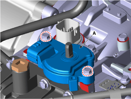
| 2. |
Install the inhibitor switch (A).
|

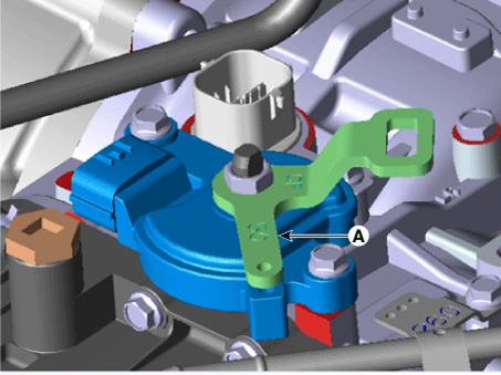
| 3. |
Install the manual control lever (A).
|
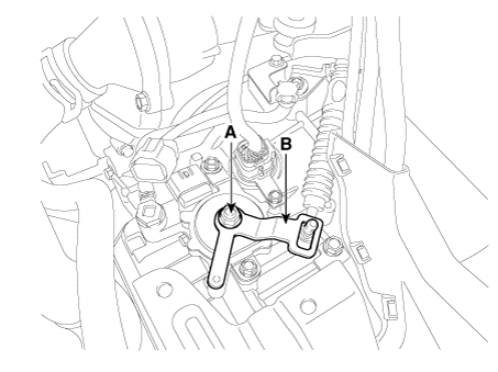
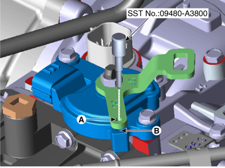
| 4. |
Align the hole (B) in the manual control lever with the "N" position
hole (A) of the inhibitor switch and then insert the SST inhibitor switch
guide pin (09480-A3800).
|
| 5. |
Tighten the manual control lever mounting nut (A).
|
| 6. |
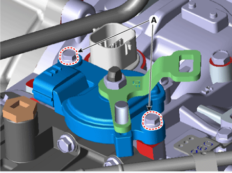
Tighten the inhibitor switch mounting bolts (A).
|
| 7. |
Remove the SST (09480-A3800) from the adjusment hole.
|
| 8. |
Connect the inhibitor switch connector (A).
|
| 9. |
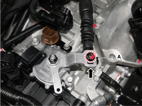
Tighten the nut (A) to the specified torque after removing free play
by pushing the shift cable in the direction of the arrow.
|
| 10. |
Install the battery and battery tray.
(Refer to Engine Electrical System - "Battery")
|
 Inhibitor Switch Troubleshooting
Troubleshooting
...
 Shift Lever Components and components location
Components
1. Shift lever knob & boots
2. Shift lever assembly
3. Shift cable assembly
...
Other information:
Kia Sportage QL (2015-2026) Service Manual: Front Seat Assembly Repair procedures
Replacement 1. Open the cover (A) and loosen the front seat mounting bolts (B). Tightening torque : 44.1 - 58.8 N·m (4.5 - 6.0 kgf·m, 32.5 - 43.4 lb·ft) [Front] [Rear] ...
Kia Sportage QL (2015-2026) Service Manual: Repair procedures
Removal • In case of bad quality or poor focus, be sure to check the camera lense surface condition and foreign materials. 1. Discon ...
Copyright © www.ksportagegl.com 2015-2026
