Kia Sportage: Brake System / Vacuum Pump Repair procedures
Kia Sportage QL (2015-2026) Service Manual / Brake System / Brake System / Vacuum Pump Repair procedures
| Remove |
[Nu 2.0 MPI/ FFV, THETA II 2.4 GDI]
| 1. |
Turn ignition switch OFF and disconnect the negative (-) battery terminal.
|
| 2. |
Remove the under cover. (Refer to Engine Mechanical System - "Engine
room under cover')
|
| 3. |
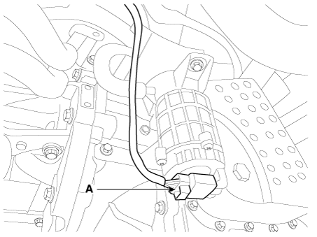
Disconnect the vacuum pumb connector (A).
|
| 4. |
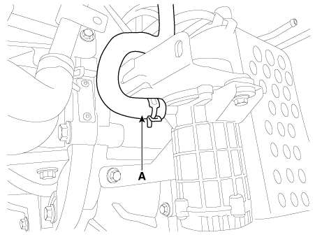
Disconnect the vacuum hose (A).
|
| 5. |
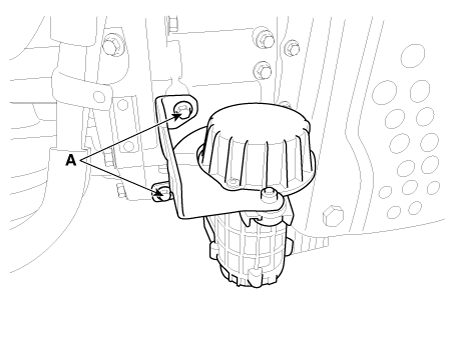
Loosen the vacuum pump bolt (A) and then remove the vaccum pump and
bracket.
|
| 6. |
Remove the bolts, and then remove the bracket from vacuum pump.
|
| 7. |
Install in the reverse order of removal.
|
[R Engine]
| 1. |
Remove the air cleaner assembly.
(Refer to Engine Mechanical System - "Air cleaner")
|
| 2. |
Remove the battery and battery tray.
(Refer to Engine Electrical System - "Battery")
|
| 3. |
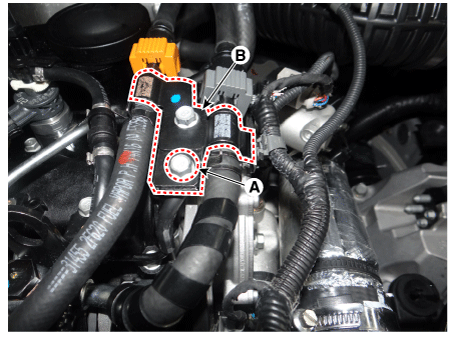
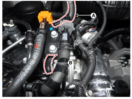
After loosening the installation bolt (A), separate the function block
bracket and fuel line (B).
|
| 4. |
After separating the booster hose (A), remove the vacuum hose (B).
|
| 5. |
After removing the clamp (A) from the intercooler hose, loosen the bolt
(B) and separate the intercooler hose (C).
|
| 6. |
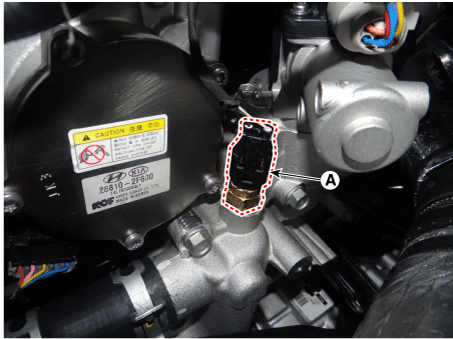
Remove the engine cooling water temperature sensor(A).
|
| 7. |
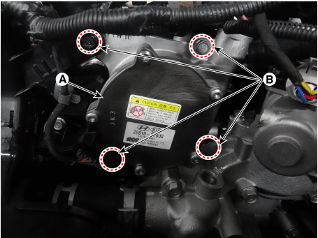
Loosen the bolts (B) and then remove the vacuum pump (A).
|
| Installation |
| 1. |
Install in the reverse order of removal.
|
| 2. |
Tighten the vacuum pump installation bolt to the specified torque.
|
| Inspection |
| 1. |
Check the brake warning lamp in the IGN ON position.
|
| 2. |
Check that the brake warning lamp is ON after releasing the parking
brake with a sufficient brake fluid level.
If the brake warning lamp is ON, check the below points.
|
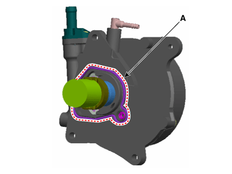
 Vacuum Pump Components and components location
Components
1. Vacuum pump
2. O -ring
1. Vacuum pump
2. O -ring
1. Vacuum pump
2. O -ring ...
 Master Cylinder Components and components location
Components
1. Reservoir
2. Screw
3. Master cylinder
...
Other information:
Kia Sportage QL (2015-2026) Service Manual: Cluster Ionizer (DATC only) Description and operation
Description The cluster ionizer disinfects and decomposes bad smell from the air conditioner or air inflow. Also, it cleans the air inside the vehicle. When the ignition is switched "ON", the ionizer runs "CLEAN" mode and then "ION" mode, swit ...
Kia Sportage QL (2015-2026) Owners Manual: Heating and air conditioning
1. Start the engine. 2. Set the mode to the desired position. For improving the effectiveness of heating and cooling; - Heating: - Cooling: 3. Set the temperature control to the desired position. 4. Set the air intake control to the outside (fresh) air position (if equipped). 5. Set the fa ...
Copyright © www.ksportagegl.com 2015-2026


