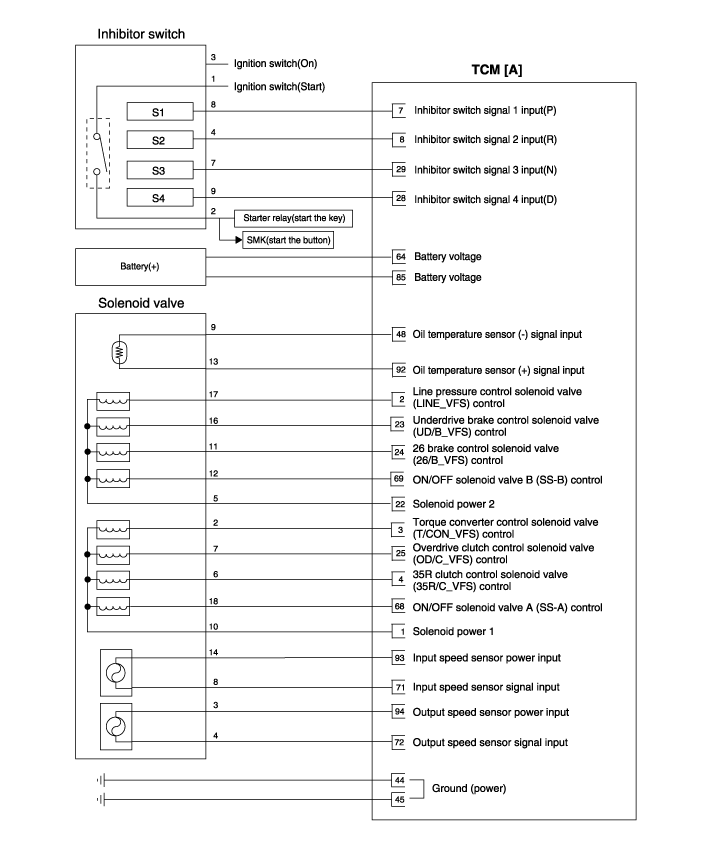
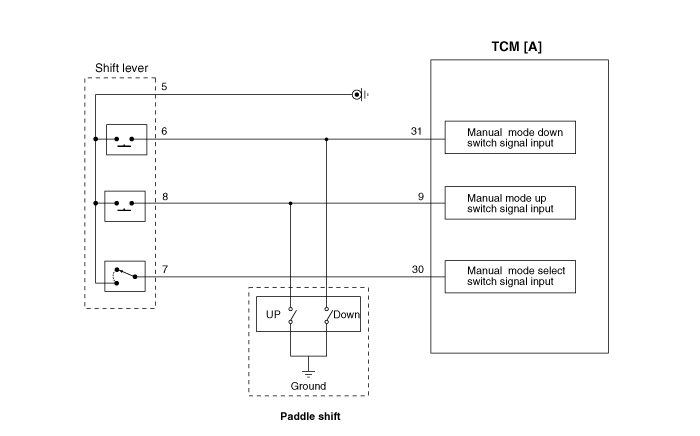
Kia Sportage: Automatic Transaxle Control System / Transaxle Control Module (TCM) Schematic diagrams
Kia Sportage QL (2015-2025) Service Manual / Automatic Transaxle System / Automatic Transaxle Control System / Transaxle Control Module (TCM) Schematic diagrams
| TCM Connector |

| TCM terminal function |
Connector [A]
|
Pin |
Description |
|
|
|
1 |
Solenoid supply power 1 |
31 |
Manual mode down switch |
|
2 |
Line pressure control solenoid valve |
45 |
Ground (Power) |
|
3 |
Torque converter control solenoid valve |
46 |
Ground (Power) |
|
4 |
35R clutch control solenoid valve |
48 |
Oil temperature sensor(-) |
|
7 |
Inhibitor switch signal "S1" |
64 |
Battery voltage(B+) |
|
8 |
Inhibitor switch signal "S2" |
68 |
ON/OFF solenoid valve A (SS-A) |
|
9 |
Manual mode up switch |
69 |
ON/OFF solenoid valve B (SS-B) |
|
22 |
Solenoid supply power 2 |
71 |
Input speed sensor signal |
|
23 |
Underdrive brake control solenoid valve |
72 |
Output speed sensor signal |
|
24 |
26 brake control solenoid valve |
85 |
Battery voltage (B+) |
|
25 |
Overdrive clutch control solenoid valve |
92 |
Oil temperature sensor (+) |
|
28 |
Inhibitor switch signal "S4" |
93 |
Input speed sensor power |
|
29 |
Inhibitor switch signal "S3" |
94 |
Output speed sensor power |
|
30 |
Manual mode select switch |
- |
- |
| TCM terminal input/ output signal |
|
Pin |
Description |
Condition |
Input/output value |
|
|
Type |
Level |
|||
|
1 |
Solenoid supply power 1 |
On |
Power |
0V/Battery voltage level |
|
Off |
9V < Battery voltage level < 16V |
|||
|
2 |
Line pressure control solenoid valve |
|
Output |
0V/Battery voltage level |
|
Low |
9V < Battery voltage level < 16V |
|||
|
3 |
Torque converter control solenoid valve |
|
Output |
0V/Battery voltage level |
|
Low |
9V < Battery voltage level < 16V |
|||
|
4 |
35R clutch control solenoid valve |
|
Output |
0V/Battery voltage level |
|
Low |
9V < Battery voltage level < 16V |
|||
|
7 |
Inhibitor switch signal "S1" |
High |
Input |
0V/Battery voltage level |
|
Low |
9V < Battery voltage level < 16V |
|||
|
8 |
Inhibitor switch signal "S2" |
High |
Input |
0V/Battery voltage level |
|
Low |
9V < Battery voltage level < 16V |
|||
|
9 |
Manual mode up switch |
Up On |
Input |
0V/Battery voltage level |
|
Other |
9V < Battery voltage level < 16V |
|||
|
22 |
Solenoid supply power 2 |
On |
Power |
0V/Battery voltage level |
|
Off |
9V < Battery voltage level < 16V |
|||
|
23 |
Underdrive brake control solenoid valve |
Low |
Output |
0V/Battery voltage level |
|
9V < Battery voltage level < 16V |
||||
|
Power supply : V_SOL2 |
||||
|
24 |
26 brake control solenoid valve |
Low |
Output |
0V/Battery voltage level |
|
9V < Battery voltage level < 16V |
||||
|
Power supply : V_SOL2 |
||||
|
25 |
Overdrive clutch control solenoid valve |
Low |
Output |
0V/Battery voltage level |
|
9V < Battery voltage level < 16V |
||||
|
Power supply : V_SOL1 |
||||
|
28 |
Inhibitor switch signal "S4" |
High |
Input |
0V/Battery voltage level |
|
Low |
9V < Battery voltage level < 16V |
|||
|
29 |
Inhibitor switch signal "S3" |
High |
Input |
0V/Battery voltage level |
|
Low |
9V < Battery voltage level < 16V |
|||
|
30 |
Manual mode select switch |
Sports mode |
Input |
0V/Battery voltage level |
|
Other |
9V < Battery voltage level < 16V |
|||
|
31 |
Manual mode down switch |
Down On |
Input |
0V/Battery
voltage level |
|
Other |
9V < Battery voltage level < 16V |
|||
|
45 |
Ground |
|
Ground |
0V |
|
46 |
Ground |
|
Ground |
0V |
|
48 |
Oil temperature sensor (-) |
|
Ground |
0V |
|
64 |
Battery voltage (B+) |
On |
Power |
0V/Battery voltage level |
|
Off |
9V < Battery voltage level < 16V |
|||
|
68 |
ON/OFF solenoid valve A (SS-A) |
High |
Output |
0V/Battery voltage level |
|
Low |
9V < Battery voltage level < 16V |
|||
|
69 |
ON/OFF solenoid valve B (SS-B) |
High |
Output |
0V/Battery voltage level |
|
Low |
9V < Battery voltage level < 16V |
|||
|
71 |
Input speed sensor signal |
High |
Input |
0.7V/1.4V |
|
Low |
||||
|
72 |
Output speed sensor signal |
High |
Input |
0.7V/1.4V |
|
Low |
||||
|
85 |
Battery voltage (B+) |
On |
Power |
0V/Battery voltage level |
|
Off |
9V < Battery voltage level < 16V |
|||
|
92 |
Oil temperature sensor (+) |
On |
Input |
0V/3.3V |
|
Off |
||||
|
93 |
Input speed sensor power |
On |
Power |
0V/7.5V |
|
Off |
||||
|
94 |
Output speed sensor power |
On |
Power |
0V/7.5V |
|
Off |
||||
| Circuit Diagram |


 Transaxle Control Module (TCM) Description and operation
Description
The module receives and processes signals from various sensors and implements
a wide range of transaxle controls to ensure optimal driving conditions for
the driver. ...
 Transaxle Control Module (TCM) Repair procedures
Inspection
1.
TCM ground circuit test : Measure the resistance between TCM and chassis
ground. (Inspect the terminal connected to the chassis ground with the
...
Other information:
Kia Sportage QL (2015-2025) Owners Manual: Securing a child restraint with the LATCH anchors system
To install a LATCH-compatible child restraint in either of the rear outboard seating positions: 1. Move the seat belt buckle away from the lower anchors. 2. Move any other objects away from the anchors that could prevent a secure connection between the child restraint and the lower anchors. 3 ...
Kia Sportage QL (2015-2025) Owners Manual: Washer fluid
Checking the washer fluid level The reservoir is translucent so that you can check the level with a quick visual inspection. Check the fluid level in the washer fluid reservoir and add fluid if necessary. Plain water may be used if washer fluid is not available. However, use washer solvent ...
Copyright © www.ksportagegl.com 2015-2025

