
Kia Sportage: Smart Parking Assist System (SPAS) / Smart Parking Assist System Unit Repair procedures
Kia Sportage QL (2015-2026) Service Manual / Body Electrical System / Smart Parking Assist System (SPAS) / Smart Parking Assist System Unit Repair procedures
| Removal |
|

| 1. |
Disconnect the negative (-) battery terminal.
|
| 2. |
Remove the smart junction block.
(Refer to Fuses And Relays - "Relay Box (Passenger Compartment)")
|
| 3. |
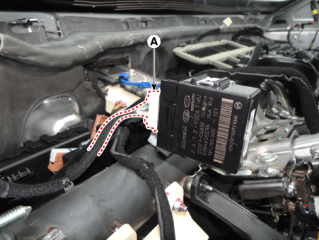
Disconnect the SPAS unit connector (A).
|
| 4. |
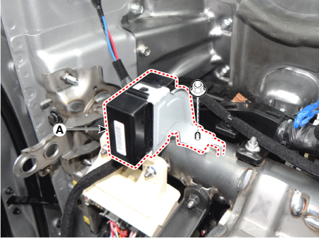
Remove the SPAS unit (A) after loosening the nut.
|
| Installation |
| 1. |
Install the SPAS unit.
|
| 2. |
Connect the SPAS unit connector.
|
| 3. |
Install the smart junction block.
|
| 4. |
Connect the negative (-) battery terminal.
|
| Inspection |
| 1. |
In the body electrical system, failure can be quickly diagnosed by using
the vehicle diagnostic system (KDS/GDS).
The diagnostic system (KDS/GDS) provides the following information.
|
| 2. |
Select the "Car model" and the 'Smart Parking Assist System (SPAS)'
to be checked in order to check the vehicle with the tester.
|
| 3. |
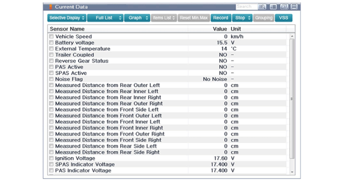
Select the 'Current Data' menu to search the current state of the input/output
data.
|
| 4. |
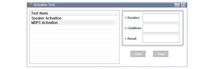
To forcibly actuate the input value of the module to be checked, select
option "Actuation Test".
|
| 5. |
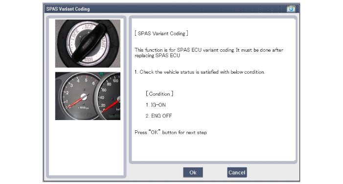
After replacing the SPAS unit with a new one, the "Variant Coding" procedure
must be performed.
|
 Smart Parking Assist System Unit Schematic diagrams
Circuit Diagram
...

Other information:
Kia Sportage QL (2015-2026) Service Manual: Front Wheel Transfer Assembly Repair procedures
Removal 1. Remove the sub frame. (Refer to Suspension System - "Sub Frame") 2. Remove the drive shaft. (Refer to Driveshaft and axle - "Front Driveshaft ") 3. Remove t ...
Kia Sportage QL (2015-2026) Service Manual: Front Impact Sensor (FIS) Repair procedures
Removal 1. Disconnect the battery negative terminal, and wait for at least thirty seconds before beginning work. 2. Disconnect the front impact sensor connector (A). 3. Remove the front impact ...
Copyright © www.ksportagegl.com 2015-2026
