Kia Sportage: Fuses And Relays / Relay Box (Passenger Compartment) Repair procedures
Kia Sportage QL (2015-2026) Service Manual / Body Electrical System / Fuses And Relays / Relay Box (Passenger Compartment) Repair procedures
| Fuse Inspection |
| 1. |
Check that the fuse holders are loosely held and that the fuses are
securely fixed by the holders.
|
| 2. |
Check that each fuse circuit has the exact fuse capacity.
|
| 3. |
Check the fuses for any damage.
|
| Diagnosis with KDS/GDS |
| 1. |
In the body electrical system, failure can be quickly diagnosed by using
the vehicle diagnostic system (KDS/GDS).
The diagnostic system (KDS/GDS) provides the following information.
|
| 2. |
Select the 'Car model' and the 'Smart Junction Block (SJB)' to be checked
in order to check the vehicle with the tester.
|
| 3. |
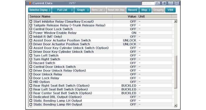
Select the 'Current Data' menu to search the current state of the input/output
data.
|
| 4. |
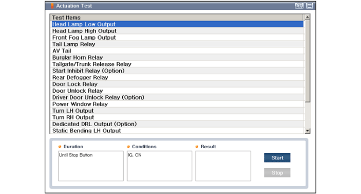
To forcibly actuate the input value of the module to be checked, select
option 'Actuation Test'
|
| 5. |
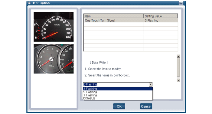
If you want to change user option, select "user option".
|
| Removal |
[Smart Junction Block]
| 1. |
Disconnect the negative (-) battery terminal.
|
| 2. |
Remove the crash pad lower panel.
(Refer to Body - "Crash Pad Lower Panel")
|
| 3. |
Disconnect the connectors (A) from the fuse side of the smart junction
block (SJB).
|
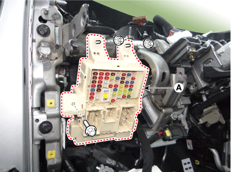
| 4. |
Remove the smart junction block (SJB) (A) after loosening the mounting
bolt and nuts.
|
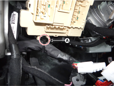
| 5. |
Remove the mounting clip (A).
|
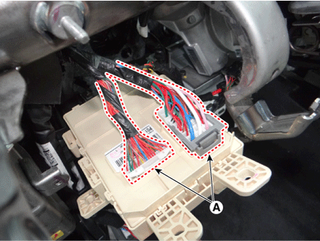
| 6. |
Disconnect the connectors (A) from the back of the smart junction block
(SJB).
|
[ICM Relay Block]
| 1. |
Disconnect the negative (-) battery terminal.
|
| 2. |
Remove the main crash pad assembly.
(Refer to Body - " Main Crash Pad Assembly")
|
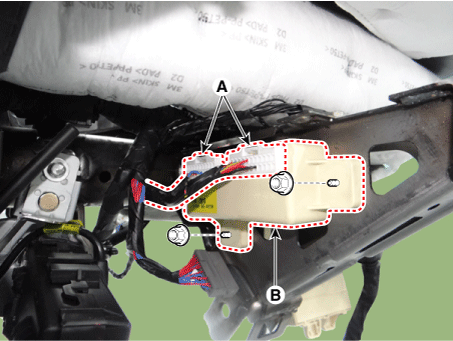
| 3. |
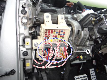
Disconnect the ICM relay block connectors (A)
|
| 4. |
Remove the ICM relay block (B) after loosening the mounting nuts.
|
| Installation |
[Smart Junction Block]
| 1. |
Connect the smart junction block (SJB) connectors.
|
| 2. |
Install the smart junction block (SJB).
|
| 3. |
Install the crash pad lower panel.
|
| 4. |
Connect the negative (-) battery terminal.
|
| 5. |
Check that all systems operate properly.
|
[ICM Relay Block]
| 1. |
Install the ICM relay block.
|
| 2. |
Connect the ICM relay block connectors.
|
| 3. |
Install the main crash pad assembly.
|
| 4. |
Connect the negative (-) battery terminal.
|
| 5. |
Check that all systems operate properly.
|
 Relay Box (Passenger Compartment) Description and operation
Description
Communication Network Diagram
Abbreviation
Expalnation
ACU
Airbag Control Unit
ABS
...
 Horn
Horn
...
Other information:
Kia Sportage QL (2015-2026) Service Manual: ETC (Electronic Throttle Control) System Description and operation
Description The Electronic Throttle Control (ETC) System consists of a throttle body with an integrated control motor and throttle position sensor (TPS). Instead of the traditional throttle cable, an Accelerator Position Sensor (APS) is used to receive driver input. The ECM ...
Kia Sportage QL (2015-2026) Service Manual: Front Seat Shield Inner Cover Repair procedures
Replacement Put on gloves to protect your hands. • Use a plastic panel removal tool to remove inter ...
Copyright © www.ksportagegl.com 2015-2026


