Kia Sportage: Engine Control System / Rail Pressure Sensor (RPS) Repair procedures
Kia Sportage QL (2015-2026) Service Manual / Engine Control / Fuel System / Engine Control System / Rail Pressure Sensor (RPS) Repair procedures
| Inspection |
| 1. |
Connect the KDS/GDS on the Data Link Connector (DLC).
|
| 2. |
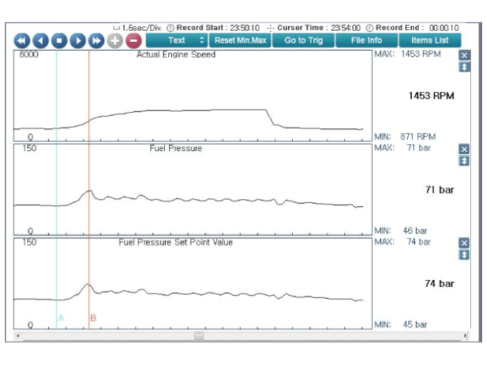
Measure the output voltage and fuel pressure of the RPS at idle and
various engine speed.
|
||||||||||||||
| Removal |
| 1. |
Release the residual pressure in fuel line.
(Refer to the Fuel Delivery System - "Release Residual Pressure in Fuel
Line")
|
| 2. |
Turn the ignition switch OFF and disconnect the battery negative (-)
terminal.
|
| 3. |
Remove the intake manifold.
(Refer to Engine Mechanical System - “Intake Manifold”)
|
| 4. |
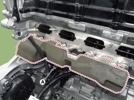
Remove the delivery pipe foam (A).
|
| 5. |
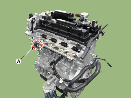
Disconnect the rail pressure sensor connector (A), and then remove the
sensor (B) from the delivery pipe.
|
| Installation |
• Install the component with the specified torques.
• Note that internal damage may occur when the component is dropped.
If the component has been dropped, inspect before installing.
|
| 1. |
Install in the reverse order of removal.
|
 Rail Pressure Sensor (RPS) Schematic diagrams
Circuit Diagram
Terminal Information
Terminal Illustration
Terminal Function
No.
Function
Connected ...
 Rail Pressure Sensor (RPS) Troubleshooting
Signal Waveform
Service data review releated with fuel pressure sensor at idle and acceleration.
(Inspect low pressure fuel line between fuel pump and high pressure pump firs ...
Other information:
Kia Sportage QL (2015-2026) Owners Manual: Accessories
If you would like additional information on the HomeLink Wireless Control System, HomeLink compatible products, or to purchase other accessories such as the HomeLink® Lighting Package, please contact HomeLink at 1-800-355-3515 or on the internet at www.homelink.com. FCC ID: NZLZTVHL3 IC: 41 ...
Kia Sportage QL (2015-2026) Service Manual: Radiator Grill Components and components location
Component Location 1. Radiator grill ...
Copyright © www.ksportagegl.com 2015-2026


