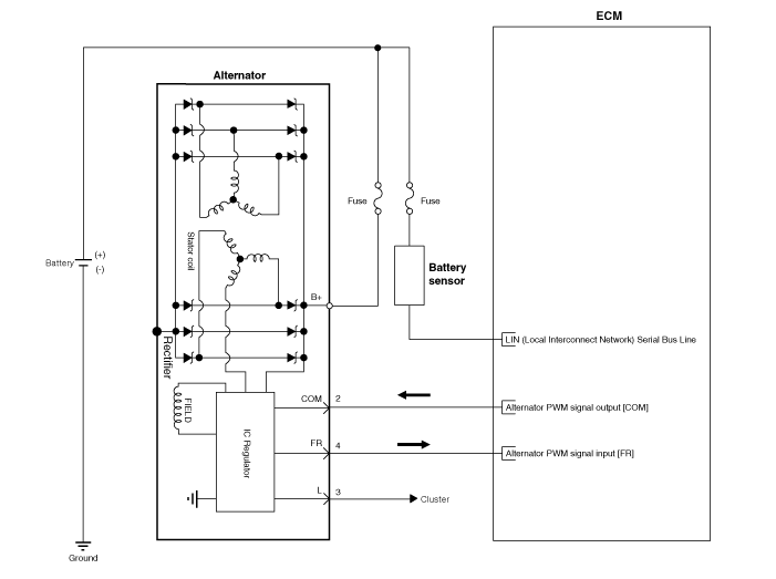
Kia Sportage: Charging System / Alternator Schematic diagrams
Kia Sportage QL (2015-2026) Service Manual / Engine Electrical System / Charging System / Alternator Schematic diagrams
| Circuit Diagram |

|
 Alternator Description and operation
Description
The Alternator has eight built-in diodes, each rectifying AC current to DC current.
Therefore, DC current appears at alternator "B" terminal.
In additi ...
 Alternator Repair procedures
Removal
1.
Turn ignition switch OFF and disconnect the battery negative (-) terminal.
2.
Remove the engine room under cover.
...
Other information:
Kia Sportage QL (2015-2026) Owners Manual: If the engine will not start
If engine doesn't turn over or turns over slowly 1. Be sure the shift lever is in N (Neutral) or P (Park) and the emergency brake is set. 2. Check the battery connections to be sure they are clean and tight. 3. Turn on the interior light. If the light dims or goes out when you operate the ...
Kia Sportage QL (2015-2026) Service Manual: Spark Plug Description and operation
Description A spark plug is a device for delivering electric current from an ignition system to the combustion chamber of a spark-ignition engine to ignite the compressed fuel/air mixture therein by means of an electric spark, while containing combustion pressure within the ...
Copyright © www.ksportagegl.com 2015-2026


