
Kia Sportage: Transfer Assembly / Front Wheel Transfer Assembly Repair procedures
Kia Sportage QL (2015-2026) Service Manual / 4 Wheel Drive (4WD) System / Transfer Assembly / Front Wheel Transfer Assembly Repair procedures
| Removal |
| 1. |
Remove the sub frame.
(Refer to Suspension System - "Sub Frame")
|
| 2. |
Remove the drive shaft.
(Refer to Driveshaft and axle - "Front Driveshaft ")
|
| 3. |
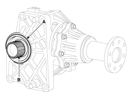
Remove the propeller shaft bolts (A) from the transfer assembly.
|
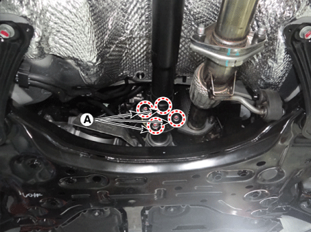
| 4. |
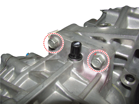
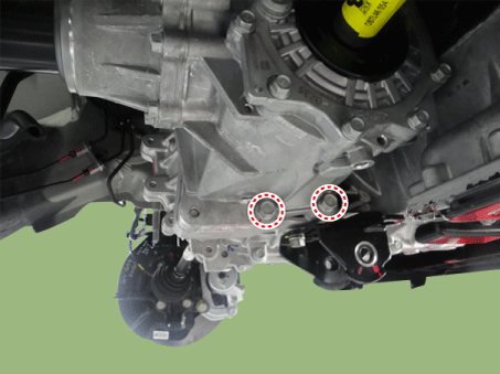
Loosen the transfer upper & lower mounting bolts. (transfer side → transaxle
side)
|
| 5. |
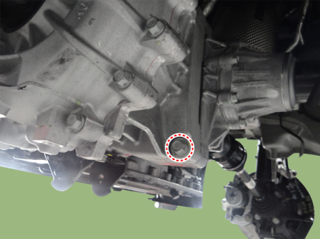
Loosen the transfer lower mounting blot. (transaxle side → transfer
side)
|
| 6. |
Remove the transfer assembly.
|
| Installation |
| 1. |
Install in the reverse order of removal.
|

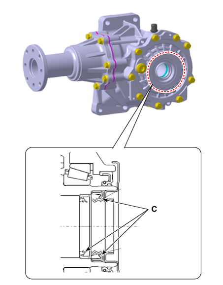
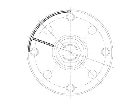
 Front Wheel Transfer Assembly Components and components location
Components Location
1. Transfer
assembly
2. Propeller shaft
3. Coupling
assembly
...
 Oil Seal Repair procedures
Replacement
[Right side]
1.
Remove the driveshaft assembly. (RH side)
(Refer to Driveshaft and axle - "Front Driveshaft ")
2. ...
Other information:
Kia Sportage QL (2015-2026) Service Manual: Repair procedures
Inspection Engine Oil Level Be sure that the vehicle is on level ground. 1. Warm up and stop the engine, and then wait for 5 minutes. 2. Turn the ...
Kia Sportage QL (2015-2026) Service Manual: Description and operation
Description Automatic transaxle control system relies on various measurements to determine the current control status and determine the necessary compensation values. These values are used to control the actuators and achieve the desired control output. Operation ...
Copyright © www.ksportagegl.com 2015-2026
