Kia Sportage: Blower / Blower Unit Repair procedures
Kia Sportage QL (2015-2026) Service Manual / Heating,Ventilation And Air Conditioning / Blower / Blower Unit Repair procedures
| Replacement |
| 1. |
Disconnect the negative (-) battery terminal.
|
| 2. |
Recover the refrigerant with a recovery/recycling/charging station.
|
| 3. |
When the engine is cool, drain the engine coolant from the radiator.
(Refer to Engine Mechanical System - “Coolant”)
|
| 4. |
Remove the cowl top cover.
(Refer to Body - "Cowl Top Cover")
|
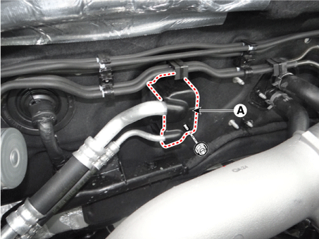
| 5. |
Remove the expansion valve cover (A) after loosening the nut.
|
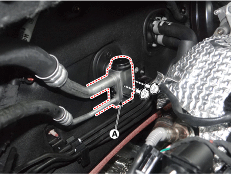
| 6. |
Remove the expansion valve (A) from the evaporator core after loosening
the bolts.
|

| 7. |
Remove the air cleaner assembly.
(Refer to Engine Mechanical System - "Air Cleaner")
|
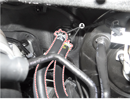
| 8. |
Disconnect the heater hoses (A).
|

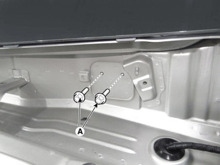
| 9. |
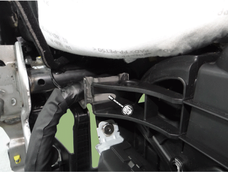
Loosen the cowl cross member mounting bolts (A).
|
| 10. |
Remove both sides of front seat assembly.
(Refer to Body - "Front Seat Assembly")
|
| 11. |
Remove the floor console.
(Refer to Body - "Floor Console")
|
| 12. |
Remove both sides of the front pillar trim.
(Refer to Body - "Front Pillar Trim")
|
| 13. |
Remove both sides of the cowl side trim.
(Refer to Body - "Cowl Side Trim")
|
| 14. |
Remove the crash pad lower panel.
(Refer to Body - "Crash Pad Lower Panel")
|
| 15. |
Remove the steering column shroud lower panel.
(Refer to Body - "Steering Column Shroud Panel")
|
| 16. |
Remove the steering wheel.
(Refer to Steering System - "Steering Wheel")
|
| 17. |
Remove the multifunction switch.
(Refer to Body Electrical System - "Multifunction Switch")
|
| 18. |
Lower the steering column after loosening the mounting bolts.
(Refer to Steering System - "Steering Column and Shaft")
|
| 19. |
Remove the front door scuff trim.
(Refer to Body - "Door Scuff Trim")
|
| 20. |
Separate the accelerator pedal (A) after loosening the bolt and nut.
|
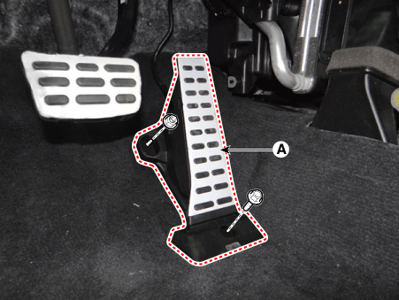
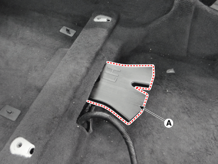
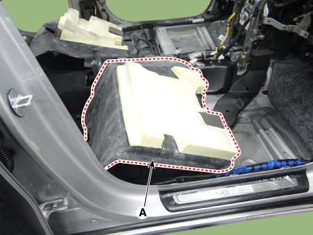
| 21. |
Remove the rear duct (A).
[LH]
[RH]
|
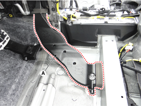
| 22. |
Separate the floor carpet (A) to allow space for removing the rear heating
duct.
[LH]
[RH]
|
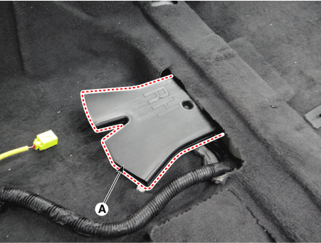
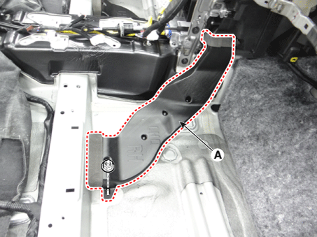
| 23. |
Remove the rear heating duct (A) after loosening the nut.
[LH]
[RH]
|
| 24. |
Remove the shift lever assembly.
(Refer to Manual Transaxle System - "Shift Lever")
(Refer to Automatic Transaxle System - "Shift Lever")
|
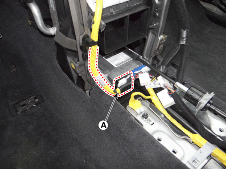
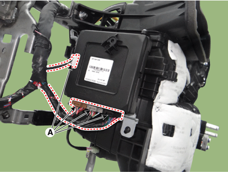
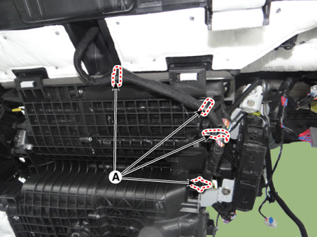
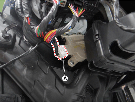
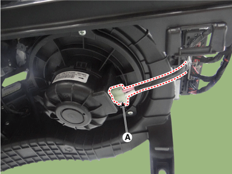
| 25. |
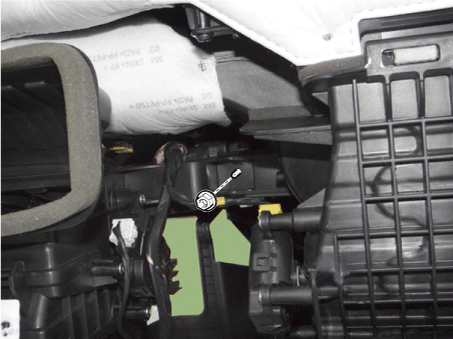
Disconnect the airbag control module (SRSCM) connector (A).
|
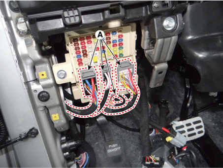
| 26. |
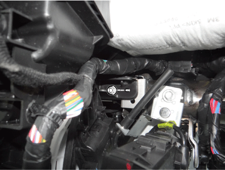
Disconnect the passenger compartment junction box connectors (A).
|
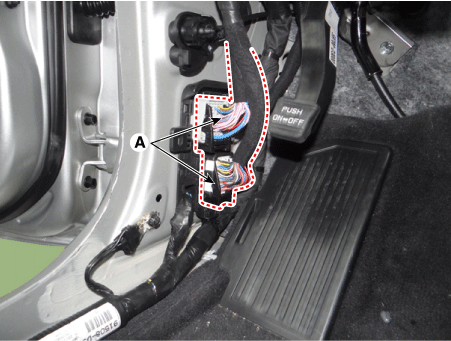
| 27. |
Disconnect the multi box connectors (A).
[LH]
[RH]
|
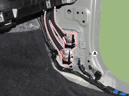
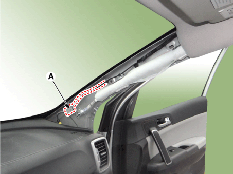
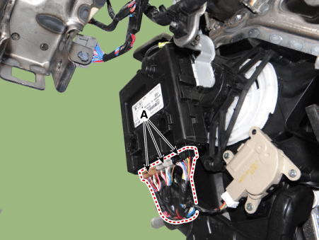
| 28. |
Disconnect the connector (A) and the mounting clips in the front pillar.
[LH]
[RH]
|
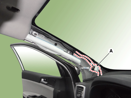
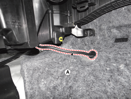
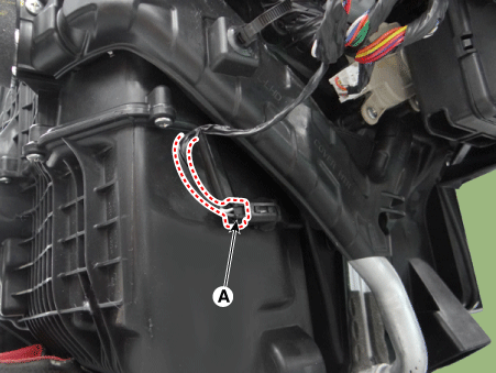
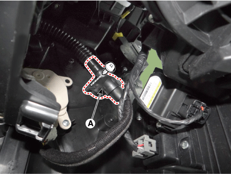
| 29. |
Remove the drain hose (A).
|
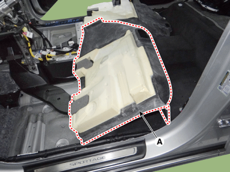
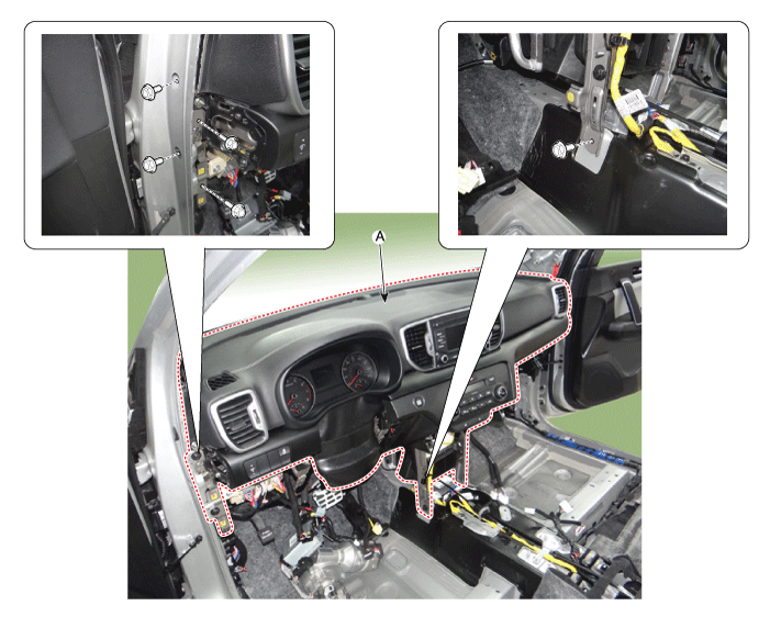
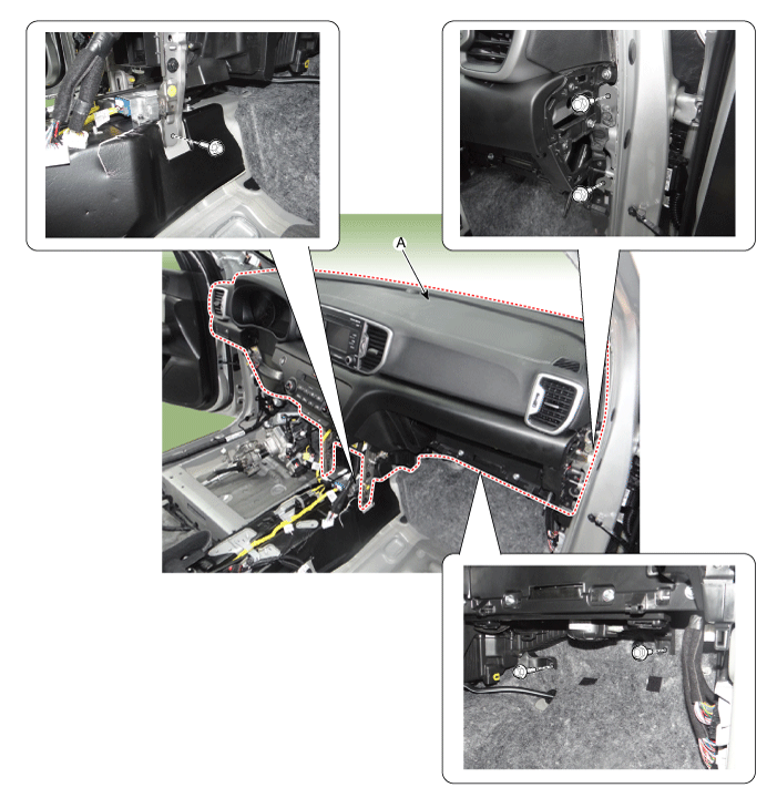
| 30. |
After loosening the bolts, remove the main crash pad and cowl cross
bar assembly (A) altogether.
[LH]
[RH]
|
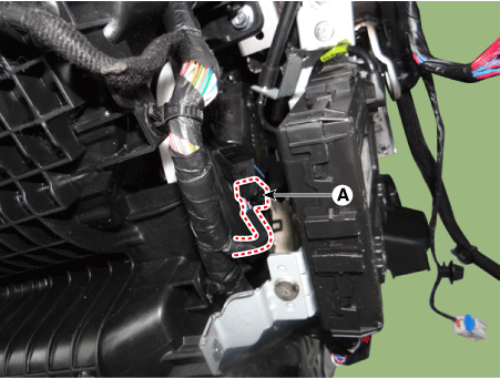
| 31. |
Disconnect the heater & blower unit connectors.
|
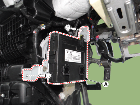
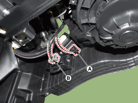
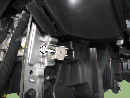
| 32. |
Remove the heater & blower unit from the main crash pad after loosening
the bolt and nuts.
|
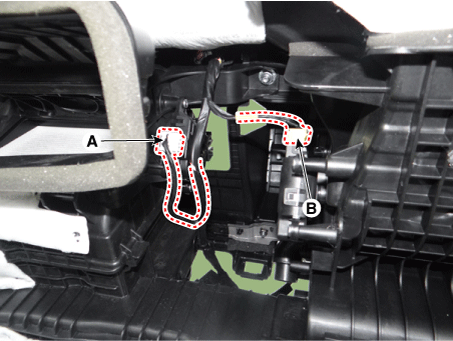
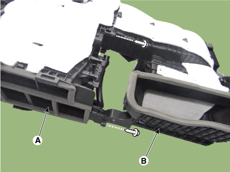
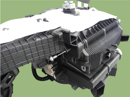
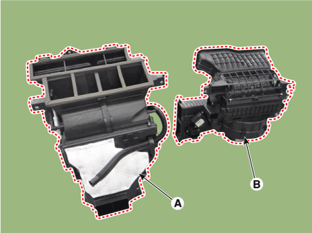
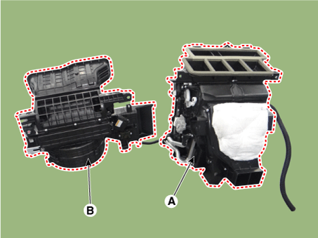
| 33. |
Remove the blower unit (B) from the heater unit (A) after loosening
the screws.
[LHD]
[RHD]
|
| 34. |
Install in the reverse order of removal.
|
 Blower Unit Components and components location
Components Location
1. Blower Unit
Components
1. Air Filter
2. Air Filter Cover
3. FET Assembly
4. Blower Resisto ...
 Blower Motor Repair procedures
Inspection
1.
Connect the battery voltage and check the blower motor rotation.
2.
If the blower motor does not operate well, ...
Other information:
Kia Sportage QL (2015-2026) Service Manual: Front Driveshaft Components and components location
Component Location (1) [Equal type] 1. Drive shaft (LH) 2. Drive shaft (RH) 3. Inner shaft bearing bracket [Unequal type] 1. Drive shaft (LH) 2. Drive shaft (RH) Component L ...
Kia Sportage QL (2015-2026) Service Manual: E-CVVT motor Troubleshooting
Signal Waveform • There is no separate sensor inside E-CVVT. Exhaust side 4-flank type target wheel is applied in order to compare CKPS and CMPS and calculate the valve timing. ...
Copyright © www.ksportagegl.com 2015-2026
